Engine parts
In an engine many parts work together and achieve the goal of converting chemical energy of fuel into mechanical energy. These parts are bolted together and the combination of all these parts is known as engine. Today I am going to tell you about these parts and how they work so you can know the basic of automobile engine.


- It is a container fitted with piston, where the fuel is burnt and power is produced.
- Cylinder is the main body of IC engine. Cylinder is a part in which the intake of fuel, compression of fuel and burning of fuel take place. The main function of cylinder is to guide the piston.
- For cooling of cylinder a water jacket (for liquid cooling used in most of cars) or fin (for air cooling used in most of bikes) are situated at the outer side of cylinder.
- At the upper end of cylinder, cylinder head and at the bottom end crank case is bolted.
- Material : Ductile (Nodular) Cast Iron ,30C8 (Low Carbon Steel)
- Manufacturing method : Casting, Forging and after that heat transfer , Machining


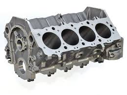
- 2) cylinder block
- One end of the cylinder is closed by means of cylinder head. This consists of inlet valve for admitting air fuel mixture and exhaust valve for removing the products of combustion.
- The inlet valve, exhaust valve, spark plug, injector etc. are bolted on the cylinder head. The main function of cylinder head is to seal the cylinder block and not to permit entry and exit of gases on cover head valve engine.
- Material: Aluminium alloys
- Manufacturing Method: Casting


3. Piston:-
- Piston is used to reciprocate inside the cylinder.
- It transmits the energy to crankshaft through connecting rod.
- Material : Aluminum Alloy 4652 because of its Low Specific Gravity.
- Manufactuirng Method: Casting


4. Piston Rings:-
- These are used to maintain a pressure tight seal between the piston and cylinder walls and also it transfer the heat from the piston head to cylinder walls.
- These rings are fitted in grooves which have been cut in the piston. They are split at one end so they can expand or slipped over the end of piston.
- Material: cast iron of fine grain and high elastic material
- Manufacturing Method: Pot casting method


5. Connecting Rod:-
- One end of the connecting rod is connected to piston through piston pin while the other is connected to crank through crank pin.
- It transmits the reciprocatory motion of piston to rotary crank.
- There are two end of connecting rod one is known as big end and other as small end. Big end is connected to the crankshaft and the small end is connected to the piston by use of piston pin.
- Material: Low Carbon steel 30C8
- Manufacturing Methods : Forging and after that heat heat treatment.


6. Crank:-
- It is a lever between connecting rod and crank shaft.
7. Crank Shaft:-
- The function of crank shaft is to transform reciprocating motion in to a rotary motion.
- The crankshaft of an internal combustion engine receives the efforts or thrust supplied by piston to the connecting rod and converts the reciprocating motion of piston into rotary motion of crankshaft.
- The crankshaft mounts in bearing so it can rotate freely.
- The shape and size of crankshaft depends on the number and arrangement of cylinders.
- Material: 37C15 Alloy Steel.
- Manufacturing Method: Casting


8. Fly wheel:-
- Fly wheel is a rotating mass used as an energy storing device.
- A flywheel is secured on the crankshaft. The main function of flywheel is to rotate the shaft during preparatory stroke. It also makes crankshaft rotation more uniform.
- Material : cast Iron
- Manufacturing Method : Casting
 |
 |
9. Crank Case:-
- It supports and covers the cylinder and the crank shaft. It is used to store the lubricating oil.
- The main body of the engine to which the cylinder are attached and which contains the crankshaft and crankshaft bearing is called crankcase. It serves as the lubricating system too and sometime it is called oil sump. All the oil for lubrication is placed in it.


10.Poppet Valves
- A valve is a device that regulates, directs or controls the flow of a fluid (gases, liquids, fluidized solids, or slurries) by opening, closing, or partially
obstructing various passageways. - The intake and exhaust valves open at the proper time to let in air and fuel and to let out exhaust.
- Note that both valves are closed during compression and combustion so that the combustion chamber is sealed.
- Materials: Phosphorus Bronze and Monel metal.


11. Spark Plug:
- The main function of a sparkplug is to conduct the high potential from the ignition system into the combustion chamber.
- It provides the proper gap across which spark is produced by applying high voltage , to ignite the mixture in the ignition chamber.
- Manufacturing Method: Each major element of the spark plug—the center electrode, the side electrode, the insulator, and the shell—is manufactured in a continuous in-line assembly process. Then, the side electrode is attached to the shell and the center electrode is fitted inside the insulator. Finally, the major parts are assembled into a single unit.


12. Engine Bearing:
- The crankshaft is supported by bearing .
- Everywhere there is rotary action in the engine , bearings are used to support the moving parts.
- Its purpose is reduce the friction and allow parts to move freely.
13. Governor:
- A device for regulating automatically output of a machine by regulating the supply of working fluid.
- When the speed decreases due to increase in load the supply valve is opened by mechanism operated by governor and the engine therefore speeds up again to its original speed.
- Thus the function of a governor is to control the fluctuations of engine speed due to changes of load.
- See: Introduction To Governors | Classification / Types Of Governors

14. Carburetor :
- The function of a carburetor is to atomize and meter the liquid fuel and mix it with the air as it enters the induction system of the engine .
- Maintaining fuel-air proportion under all conditions of operation appropriate to the conditions.

- Fuel injection is a system for mixing fuel with air in an internal combustion engine. It has become the primary fuel delivery system used in automotive petrol engines, having almost completely replacarburetorstors in the late 1980s.
- The primary difference between carburettors and fuel injection is that fuel injection atomizes the fuel by forcibly pumping it through a small nozzle under high pressure, while a carburettor relies on low pressure created by intake air rushing through it to add the fuel to the airstream.
- The fuel injector is only a nozzle and a valve: the power to inject the fuel comes from a pump or a pressure container farther back in the fuel supply.
16. Manifold
- The main function of manifold is to supply the air fuel mixture and collects the exhaust gases equally form all cylinder. In an internal combustion engine two manifold are used, one for intake and other for exhaust.
- Material : Aluminium alloy -Alloy 4600


| 17. Gudgeon pin or piston pin |
- These are hardened steel parallel spindles fitted through the piston bosses and the small end bushes or eyes to allow the connecting rods to swivel. It connects the piston to connecting rod. It is made hollow for lightness.
- Material: Plain Carbon steel 10C4

 18. Pushrod
- Pushrod is used when the camshaft is situated at the bottom end of cylinder. It carries the camshaft motion to the valves which are situated at the cylinder head.


| 19. Rocker Arm : |
- Rocker Arms are typically in between the pushrod and the intake and exhaust valves. They allow the pushrods to push up on the rocker arms and therefore push down on the valves.
- Material : Medium Carbon steel
- Manufacturing methods : Forging

| 20.Cam Shaft: |
- Camshaft is used in IC engine to control the opening and closing of valves at proper timing.
- For proper engine output inlet valve should open at the end of exhaust stroke and closed at the end of intake stroke.
- So to regulate its timing, a cam is use which is oval in shape and it exerts a pressure on the valve to open and release to close.
- It is drive by the timing belt which drives by crankshaft. It is placed at the top or at the bottom of cylinder.
- Material: Plain Carbon steel 10C4
- Manufacturing Method: Grinding, Case Hardening


- Copyrights learnmech

Comments
Post a Comment